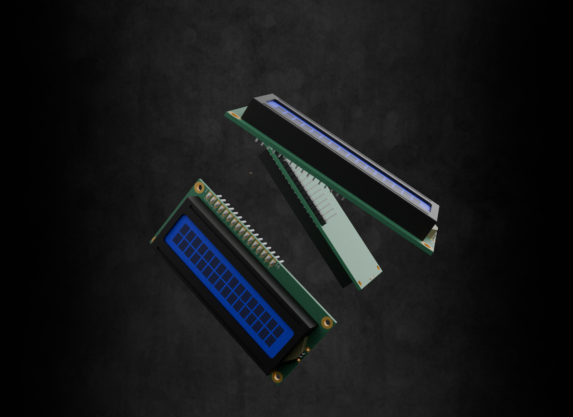
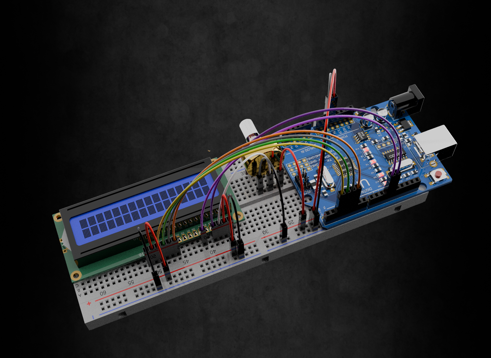
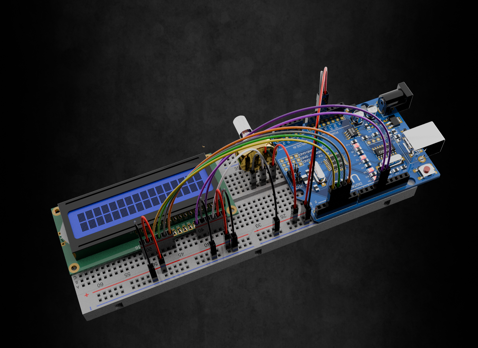
Connecting 16x2 LCD to Arduino
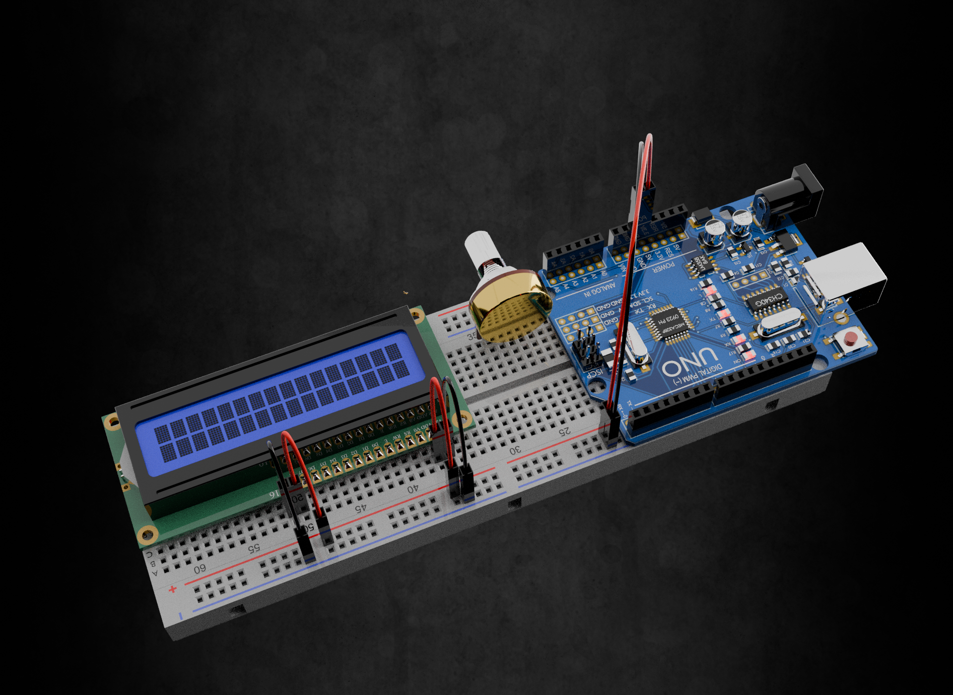
Step 1: Power Connections - Getting the Basics Right
Before anything else, your LCD needs power to function. There are three power-related connections:
VCC and VSS (Pins 2 and 1)
- VCC (Pin 2) → Arduino 5V: This powers the LCD's internal logic circuits
- VSS (Pin 1) → Arduino GND: This provides the ground reference for the entire display
Think of these like plugging any electronic device into the wall - without power, nothing else matters.
Backlight Power (Pins 15 and 16)
- LED+ (Pin 15) → 5V through 220Ω resistor: Powers the backlight LEDs
- LED- (Pin 16) → GND: Completes the backlight circuit
Why the resistor? LEDs can burn out if given too much current. The 220Ω resistor limits current to a safe level while keeping the backlight bright enough to see.
Pro tip: You can actually use the LCD without the backlight connections if you're in a well-lit area - it will still display text, just without the blue glow behind it.
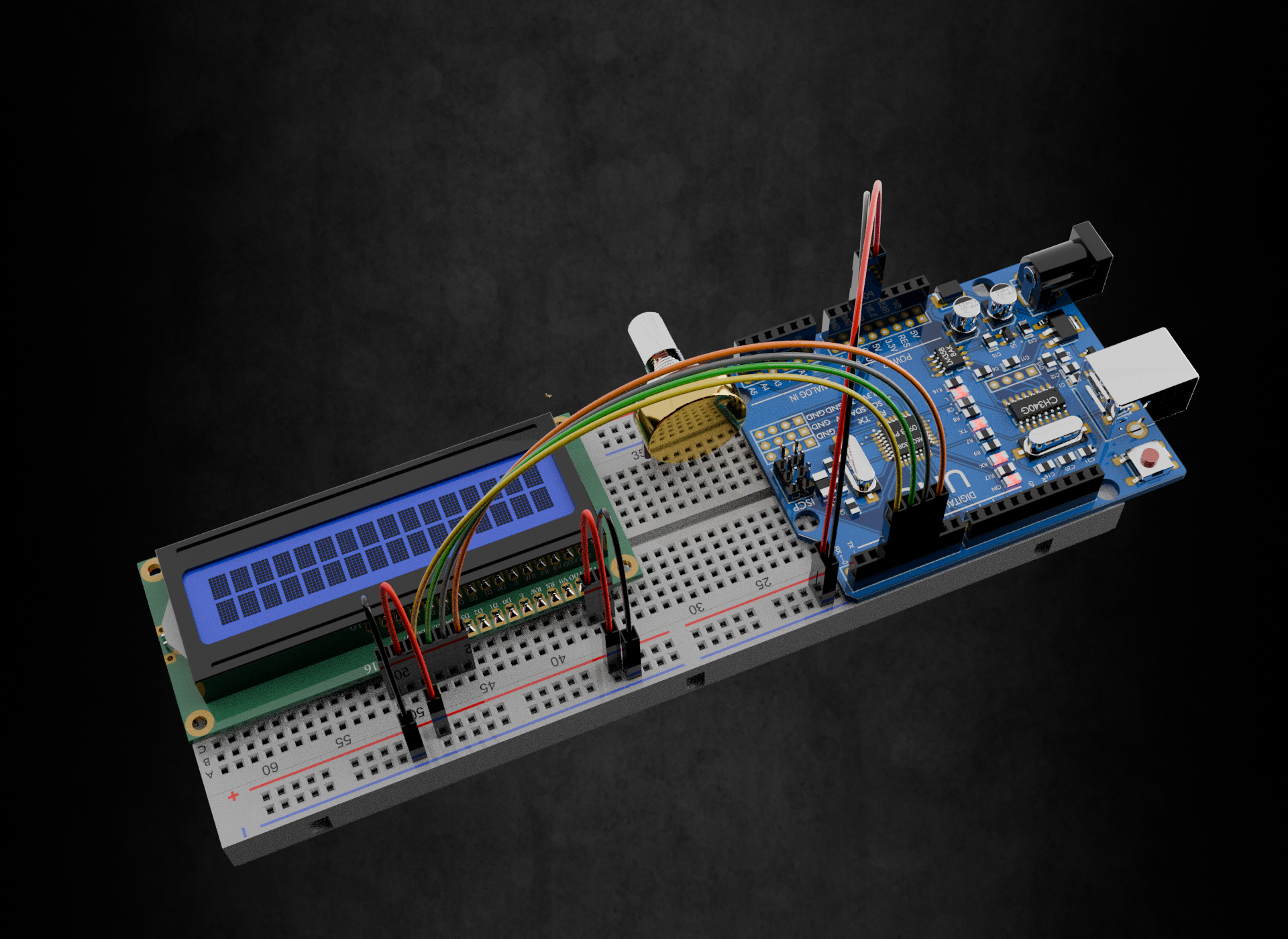
Step 2: The Data Highway - 4 Wires That Carry All Information
Here's where it gets interesting. The LCD controller actually expects 8 bits of data (8 wires), but we're only using 4 wires. How?
Data Pins (D4-D7 connecting to D4-D7 on LCD)
- LCD D4 → Arduino Pin 5
- LCD D5 → Arduino Pin 4
- LCD D6 → Arduino Pin 3
- LCD D7 → Arduino Pin 2
The clever part: We send data in two chunks. First, we send the upper 4 bits of our 8-bit data, then we send the lower 4 bits. It's like sending a long message by breaking it into two shorter messages.
For example, to send the letter "A" (which is 01000001 in binary):
- First chunk: Send 0100 on D4-D7
- Second chunk: Send 0001 on D4-D7
Why pins 2-5? These pins are conveniently located next to each other on most Arduino boards, making wiring cleaner and easier to troubleshoot.
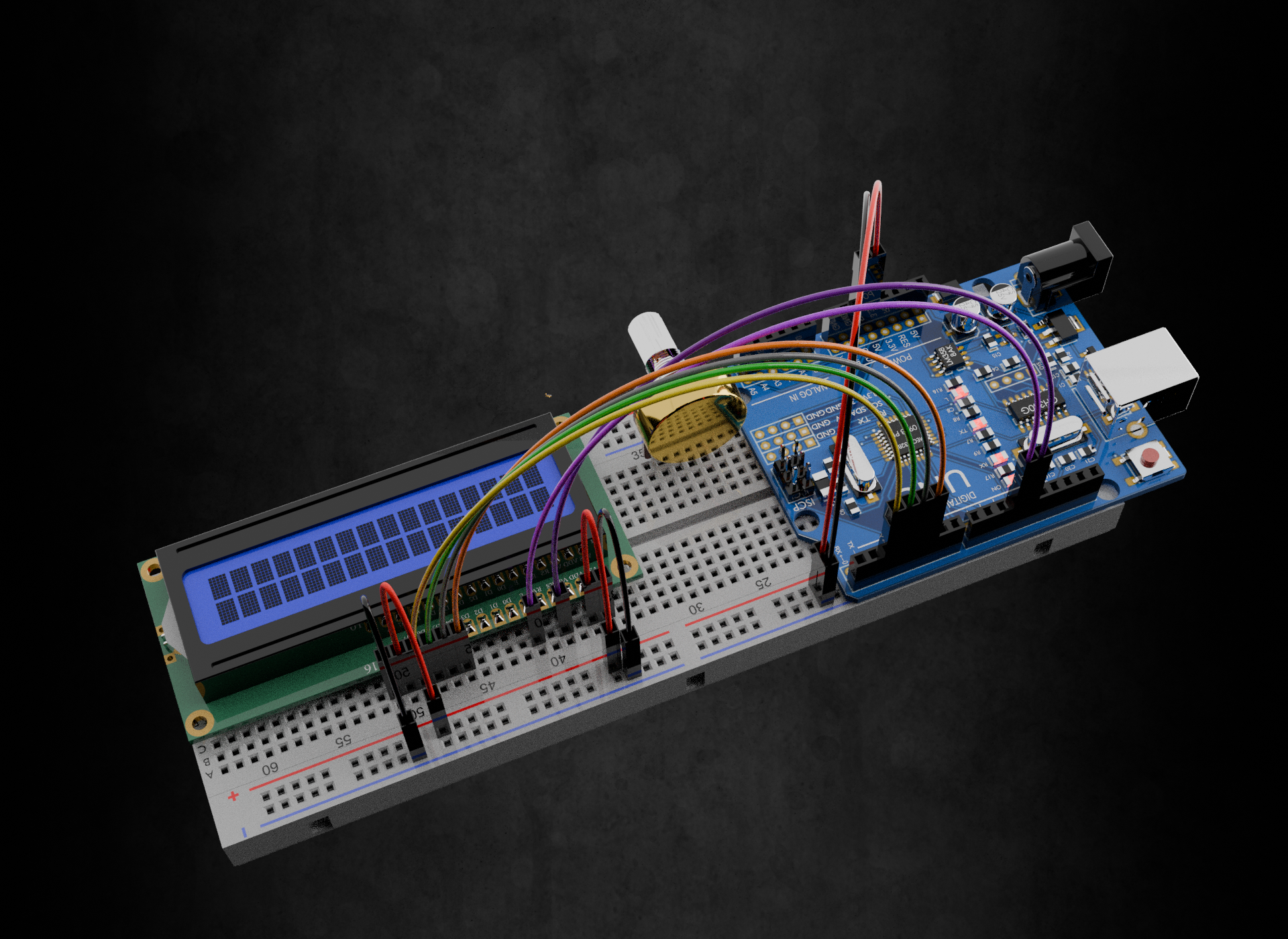
Step 3: The Control Signals - RS and Enable
These two pins are the "brain" of the operation - they tell the LCD how to interpret the data you're sending.
RS - Register Select (Pin 4 on LCD)
LCD RS → Arduino Pin 12
Think of RS as a switch with two positions:
- RS = LOW (0V): "I'm sending you a COMMAND" (like clear screen, move cursor)
- RS = HIGH (5V): "I'm sending you TEXT to display" (like letters, numbers, symbols)
Enable - The Execute Button (Pin 6 on LCD)
LCD Enable → Arduino Pin 11
Enable is like a doorbell - nothing happens until you ring it! The sequence is:
- Set up your data on D4-D7 wires
- Set RS to indicate command or text
- Pulse Enable from HIGH to LOW
- LCD reads everything and acts on it
The timing matters: The Enable pulse needs to be at least 450 nanoseconds long, but Arduino's digitalWrite() is plenty slow enough that you don't need to worry about this.
Step 4: Contrast Control - The Potentiometer Connection
Ever wonder why sometimes LCD displays show dark blocks or barely visible text? That's a contrast issue.
V0 - Contrast Pin (Pin 3 on LCD)
LCD V0 → Middle pin of 10kΩ potentiometer
- Potentiometer side 1 → 5V
- Potentiometer side 2 → GND
How it works: The potentiometer creates a variable voltage between 0V and 5V. This voltage controls how dark the pixels appear:
- Voltage too high = invisible text
- Voltage too low = dark blocks
- Sweet spot (usually 0.4V - 1V) = clear, readable text
Pro tip: Start with the potentiometer in the middle position, then adjust until text is clearly visible.
Step 5: R/W Pin - The Forgotten Connection
Read/Write Select (Pin 5 on LCD)
LCD R/W → Arduino GND
This pin determines whether you're reading from or writing to the LCD:
- R/W = HIGH: Read mode (LCD sends data to Arduino)
- R/W = LOW: Write mode (Arduino sends data to LCD)
Why tie it to ground? In 99% of projects, we only write TO the display (showing text), never read FROM it. By connecting R/W to ground, we permanently set it to write mode, which simplifies our code and wiring.
When would you read from an LCD? Advanced applications might read the LCD's status to check if it's busy processing a command, but the Arduino LiquidCrystal library handles this automatically with timing delays.
LCD WIRING CONNECTIONS:
Pin 1 VSS - Connect to Arduino GND (Ground reference)
Pin 2 VCC - Connect to Arduino 5V (Power supply)
Pin 3 V0 - Connect to Potentiometer middle pin (Contrast control)
Pin 4 RS - Connect to Arduino Pin 12 (Command/Data select)
Pin 5 R/W - Connect to Arduino GND (Read/Write always write)
Pin 6 Enable - Connect to Arduino Pin 11 (Execute signal)
Pin 7 D0 - Not connected (Lower data bits unused)
Pin 8 D1 - Not connected (Lower data bits unused)
Pin 9 D2 - Not connected (Lower data bits unused)
Pin 10 D3 - Not connected (Lower data bits unused)
Pin 11 D4 - Connect to Arduino Pin 5 (Data bit 4)
Pin 12 D5 - Connect to Arduino Pin 4 (Data bit 5)
Pin 13 D6 - Connect to Arduino Pin 3 (Data bit 6)
Pin 14 D7 - Connect to Arduino Pin 2 (Data bit 7)
Pin 15 LED+ - Connect to 5V through 220 ohm resistor (Backlight power)
Pin 16 LED- - Connect to Arduino GND (Backlight ground)
POTENTIOMETER CONNECTIONS:
Side 1 - Connect to Arduino 5V
Middle wiper - Connect to LCD Pin 3 (V0)
Side 2 - Connect to Arduino GND
The Basic Code to Test Your Connection
#include <LiquidCrystal.h>

// Initialize library with interface pins
LiquidCrystal lcd(12, 11, 5, 4, 3, 2);
//                RS  E  D4 D5 D6 D7

void setup() {
  // Set up LCD's columns and rows:
  lcd.begin(16, 2);
  // Print a message
  lcd.print("Hello, World!");
}

void loop() {
  // Set cursor to column 0, line 1
  lcd.setCursor(0, 1);
  // Print the number of seconds since reset
  lcd.print(millis() / 1000);
}
Troubleshooting Tips
No display at all? Check power connections (VCC and VSS) first.
Dark blocks everywhere? Adjust the contrast potentiometer.
Garbled text? Double-check your data wire connections (D4-D7).
Display works but no backlight? Check LED+ and LED- connections, and make sure your resistor is working.
Why This Matters
Understanding these connections transforms the "scary 16-wire LCD" into a logical system:
- 4 wires for power and backlight (straightforward)
- 4 wires for data (sends information in chunks)
- 2 wires for control (RS says what kind of data, Enable says when to read it)
- 1 wire for contrast (makes text visible)
- 1 wire tied to ground (simplifies operation)
Once you grasp this logic, you'll never need to Google "Arduino LCD wiring" again - you'll understand exactly what each wire does and why it's there!